Static IP Clash Resolution Manual
Configuring 6 identical devices locked to IP address 192.168.100.100 using VLAN VRF Isolation & Mangle DST-NAT
This procedure generates the exact configuration running on your MikroTik device (RouterOS 7.20.7):
- VLAN Interfaces Attached to Bridge: VLANs 10–60 are created on top of
bridge, allowing tagged traffic via bridge member ports. - RouterOS v7 Explicit VRFs: VRFs 10–60 created under
/ip vrfand bound to their respectivevlan10–60interfaces. - Dual IP Alias Addressing: Both gateway subnets (
192.168.X.1/24) and local target subnets (192.168.100.1/24) are assigned to each VLAN interface. - Disabled FastTrack: Disabled in firewall filter rules to guarantee connection tracking and VRF policy routing integrity.
- Pre-NAT Mangle & Static Subnet Leaking: Forces alias traffic into target VRFs and leaks responses back to the local management PC on
192.168.88.0/24.
Step 1 Configure the TP-Link Managed Switch
What this does: Isolates each of your 6 duplicate devices into their own distinct Layer 2 broadcast domains (VLANs 10 through 60) so they cannot see or conflict with each other. It then bundles all these VLANs together on Port 8 (the trunk port) to send to your router.
1. Port Mapping Table
Connect your cables exactly as shown below:
| Switch Port | Connected To | VLAN Assignment | Port Mode |
|---|---|---|---|
| Port 1 | Device #1 (192.168.100.100) | VLAN 10 | Access (Untagged) |
| Port 2 | Device #2 (192.168.100.100) | VLAN 20 | Access (Untagged) |
| Port 3 | Device #3 (192.168.100.100) | VLAN 30 | Access (Untagged) |
| Port 4 | Device #4 (192.168.100.100) | VLAN 40 | Access (Untagged) |
| Port 5 | Device #5 (192.168.100.100) | VLAN 50 | Access (Untagged) |
| Port 6 | Device #6 (192.168.100.100) | VLAN 60 | Access (Untagged) |
| Port 7 | Temporary Management / Unused | VLAN 1 (Default Management) | Access (Untagged) |
| Port 8 | MikroTik Router (Ether2/3/4/5 or SFP1 on Bridge) | VLANs 10, 20, 30, 40, 50, 60 | Trunk (Tagged) |
2. TP-Link Switch Web Interface Steps
- Connect your PC to Port 7, open a browser, and log into your TP-Link Switch management page (usually
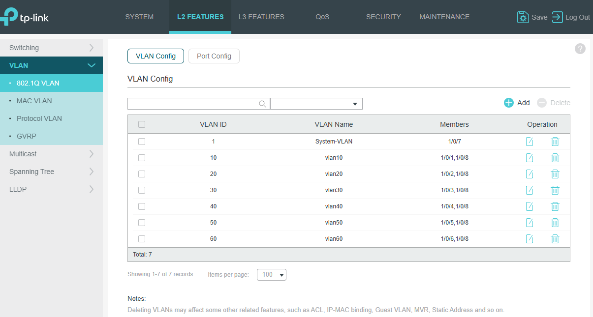
192.168.0.1or192.168.1.1). - Navigate to L2 Features > VLAN > 802.1Q VLAN.
- Create the VLANs and assign the ports carefully:
- Create VLAN 10: Mark Port 1 as Untagged, and Port 8 as Tagged.
- Create VLAN 20: Mark Port 2 as Untagged, and Port 8 as Tagged.
- Create VLAN 30: Mark Port 3 as Untagged, and Port 8 as Tagged.
- Create VLAN 40: Mark Port 4 as Untagged, and Port 8 as Tagged.
- Create VLAN 50: Mark Port 5 as Untagged, and Port 8 as Tagged.
- Create VLAN 60: Mark Port 6 as Untagged, and Port 8 as Tagged.
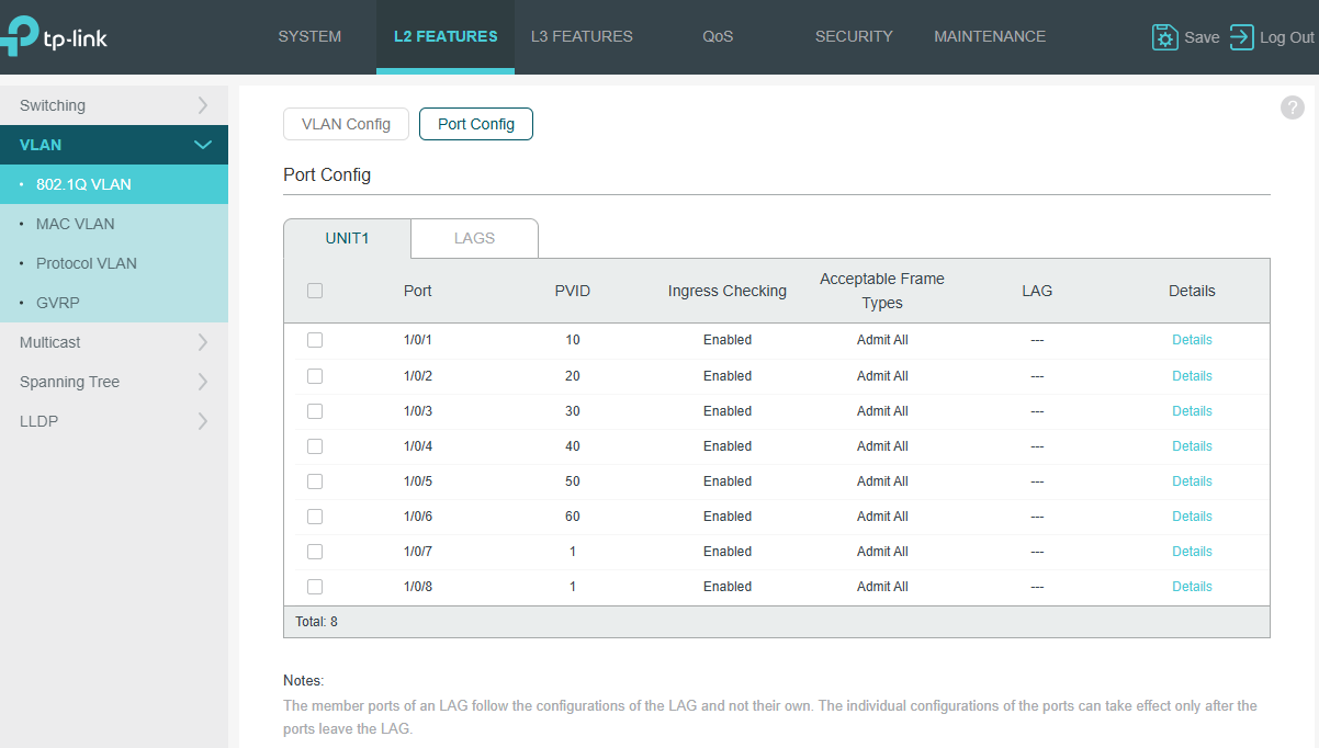
- Navigate to the Port Config / PVID settings tab:
- Set the PVID for Port 1 to
10. - Set the PVID for Port 2 to
20. - Set the PVID for Port 3 to
30. - Set the PVID for Port 4 to
40. - Set the PVID for Port 5 to
50. - Set the PVID for Port 6 to
60. - Keep Port 7 on PVID 1 and Port 8 on PVID 1.
- Set the PVID for Port 1 to
- Click Save Config at the top of the interface so settings persist across reboots.
3. Switch Configuration Screenshots
Refer to the switch screenshots below for the exact web interface layout and configurations. Click any image or button to view full size:
802.1Q VLAN Settings
Port PVID Configuration
Step 2 Configure the MikroTik Router (WinBox)
What this does: Recreates your exact MikroTik configuration: VLANs attached to bridge, RouterOS v7 VRF instances, dual IP address assignments, disabled FastTrack filter rule, Pre-NAT Mangle rules, Destination NAT, Masquerade, and VRF static leaking routes.
Download the RouterOS configuration files directly below to import or reference in your project:
- Mikrotik-default-config.txt — The main MikroTik RouterOS script export.
- clean_vrf_nat_backup.rsc — Cleaned RouterOS script focusing only on the VRF, NAT, Mangle, and routing definitions.
- restore_point.backup — Complete binary system backup restore point.
Physical Connection:
Run a network cable from Port 8 (Trunk) of your TP-Link Switch into any active bridge port on the MikroTik (such as Ether2, Ether3, Ether4, or Ether5).
How to do it (Copy-Paste Terminal Script):
Open WinBox, connect to your MikroTik, open the Terminal (from the left menu), and paste the following commands:
# ==============================================================================
# 1. CREATE VLAN INTERFACES ON BRIDGE
# ==============================================================================
/interface vlan
add interface=bridge name=vlan10 vlan-id=10
add interface=bridge name=vlan20 vlan-id=20
add interface=bridge name=vlan30 vlan-id=30
add interface=bridge name=vlan40 vlan-id=40
add interface=bridge name=vlan50 vlan-id=50
add interface=bridge name=vlan60 vlan-id=60

# ==============================================================================
# 2. CREATE VRF INSTANCES AND ASSIGN VLAN INTERFACES
# ==============================================================================
/ip vrf
add interfaces=vlan10 name=vrf10
add interfaces=vlan20 name=vrf20
add interfaces=vlan30 name=vrf30
add interfaces=vlan40 name=vrf40
add interfaces=vlan50 name=vrf50
add interfaces=vlan60 name=vrf60

# ==============================================================================
# 3. ASSIGN DUAL IP ADDRESSES TO VLAN INTERFACES
# ==============================================================================
/ip address
add address=192.168.10.1/24 interface=vlan10 network=192.168.10.0
add address=192.168.20.1/24 interface=vlan20 network=192.168.20.0
add address=192.168.30.1/24 interface=vlan30 network=192.168.30.0
add address=192.168.40.1/24 interface=vlan40 network=192.168.40.0
add address=192.168.50.1/24 interface=vlan50 network=192.168.50.0
add address=192.168.60.1/24 interface=vlan60 network=192.168.60.0

add address=192.168.100.1/24 interface=vlan10 network=192.168.100.0
add address=192.168.100.1/24 interface=vlan20 network=192.168.100.0
add address=192.168.100.1/24 interface=vlan30 network=192.168.100.0
add address=192.168.100.1/24 interface=vlan40 network=192.168.100.0
add address=192.168.100.1/24 interface=vlan50 network=192.168.100.0
add address=192.168.100.1/24 interface=vlan60 network=192.168.100.0

# ==============================================================================
# 4. DISABLE FASTTRACK (CRITICAL FOR VRFS AND NAT POLICY ROUTING)
# ==============================================================================
/ip firewall filter
set [find comment~"fasttrack"] disabled=yes

# ==============================================================================
# 5. MANGLE ROUTING MARKS (PREROUTING INTO VRFS)
# ==============================================================================
/ip firewall mangle
add action=mark-routing chain=prerouting dst-address=192.168.10.100 new-routing-mark=vrf10
add action=mark-routing chain=prerouting dst-address=192.168.20.100 new-routing-mark=vrf20
add action=mark-routing chain=prerouting dst-address=192.168.30.100 new-routing-mark=vrf30
add action=mark-routing chain=prerouting dst-address=192.168.40.100 new-routing-mark=vrf40
add action=mark-routing chain=prerouting dst-address=192.168.50.100 new-routing-mark=vrf50
add action=mark-routing chain=prerouting dst-address=192.168.60.100 new-routing-mark=vrf60

# ==============================================================================
# 6. DESTINATION NAT & SOURCE NAT (MASQUERADE)
# ==============================================================================
/ip firewall nat
add action=dst-nat chain=dstnat dst-address=192.168.10.100 to-addresses=192.168.100.100
add action=dst-nat chain=dstnat dst-address=192.168.20.100 to-addresses=192.168.100.100
add action=dst-nat chain=dstnat dst-address=192.168.30.100 to-addresses=192.168.100.100
add action=dst-nat chain=dstnat dst-address=192.168.40.100 to-addresses=192.168.100.100
add action=dst-nat chain=dstnat dst-address=192.168.50.100 to-addresses=192.168.100.100
add action=dst-nat chain=dstnat dst-address=192.168.60.100 to-addresses=192.168.100.100

add action=masquerade chain=srcnat out-interface=vlan10
add action=masquerade chain=srcnat out-interface=vlan20
add action=masquerade chain=srcnat out-interface=vlan30
add action=masquerade chain=srcnat out-interface=vlan40
add action=masquerade chain=srcnat out-interface=vlan50
add action=masquerade chain=srcnat out-interface=vlan60

# ==============================================================================
# 7. RETURN PATH ROUTES (LEAKING PC SUBNET INTO VRFS)
# ==============================================================================
/ip route
add dst-address=192.168.88.0/24 gateway=bridge routing-table=vrf10
add dst-address=192.168.88.0/24 gateway=bridge routing-table=vrf20
add dst-address=192.168.88.0/24 gateway=bridge routing-table=vrf30
add dst-address=192.168.88.0/24 gateway=bridge routing-table=vrf40
add dst-address=192.168.88.0/24 gateway=bridge routing-table=vrf50
add dst-address=192.168.88.0/24 gateway=bridge routing-table=vrf60
Step 3 Configure Your Local Windows PC
What this does: Configures Windows static routes so your PC knows to send packets bound for the logical target subnets (192.168.10.0/24 through 60.0/24) directly to the MikroTik router interface (192.168.88.1).
Physical Connection:
Plug your PC's Ethernet port into any spare port on the MikroTik bridge (e.g., Ether2, Ether3, Ether4, or Ether5) on the main LAN subnet (192.168.88.0/24).
Open Command Prompt (cmd) as Administrator on Windows and execute the following commands. Using the
-p flag ensures the routes persist even after a system reboot:
route -p add 192.168.10.0 mask 255.255.255.0 192.168.88.1
route -p add 192.168.20.0 mask 255.255.255.0 192.168.88.1
route -p add 192.168.30.0 mask 255.255.255.0 192.168.88.1
route -p add 192.168.40.0 mask 255.255.255.0 192.168.88.1
route -p add 192.168.50.0 mask 255.255.255.0 192.168.88.1
route -p add 192.168.60.0 mask 255.255.255.0 192.168.88.1To communicate with each duplicate device, simply direct your web browser, terminal, or API request to its corresponding virtual IP address:
- Device on Switch Port 1:
192.168.10.100 - Device on Switch Port 2:
192.168.20.100 - Device on Switch Port 3:
192.168.30.100 - Device on Switch Port 4:
192.168.40.100 - Device on Switch Port 5:
192.168.50.100 - Device on Switch Port 6:
192.168.60.100